MODELLING A GLASS
By Olivier Saraja (http://www.linuxgraphic.org)
S t e p 1 :
Start a new session by reinitializing Blender (CTRL+X). The default plane, selected and appearing in pink, will symbolize the table on which our glass will lay upon. In the top view (NUM-7), resize the plane until it gets around five times its actuel shape ("S"-KEY, move the mouse cursor while maintaining the CTRL key pressed in order to get tabulated size increments).
Now shift into front view (NUM-1) in order to start the modelling of the glass. We will first draw a cross-section, and we will make it spin around a central axis in order to get, by vertices duplication, the whole shape of the glass.
We start by adding a mesh plane (SPACE>ADD>MESH>Plane). We now select all the vertices of the mesh ("A"-KEY) and delete them ("X"-KEY). We now add, by hand and at the exact locations that interest us, the vertices that will build our cross-section. To do this, we will keep pressed the SHIFT and CTRL keys, and we will click with the left mouse button. New vertices will appear where you pressed the mouse button, linked by a edge to the previous vertex. You can now close your cross-section by unselecting all the vertices ("A"-KEY as many times as necessary) and by selecting ("B"-KEY) the two vertices to close. Once done, press the "F"-KEY to close the section.
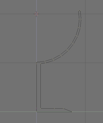
You now have a general cross-section, and you can reorder its vertices by moving them in more accurate location with the "G"-KEY.
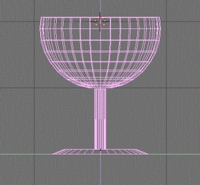
Once finished, you should have a cross-section looking like this one.
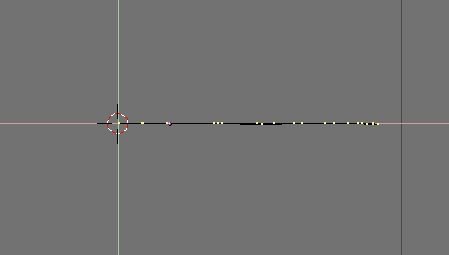
Place the cursor as indicated on the previous picture, in order to specify to Blender the location of the spinning axis. If needed, press SHIFT-"S" and select 'SNAP Curs -> Grid'.
S t e p 2 :
Toggle into top view (NUM-7) and make sure the cursor is at the right place. Also make sure you are in Edit mode (TAB) and that all the vertices are selected ("A"-KEY).
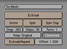
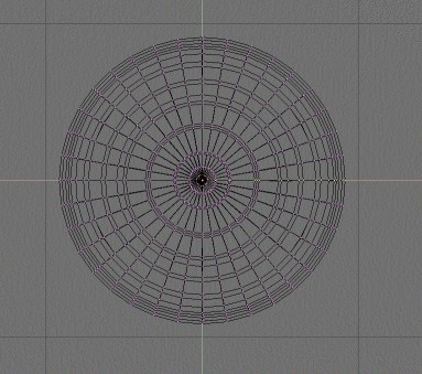
Display the Edit Buttons ("F9"-KEY) and set these parameters to these values : Degr: 360, Steps: 36 then press the Spin button. You should get the following result.
 |
 |
Leave the Edit mode (TAB) and toggle to side or face view (NUM-3 or NUM-1) to have a more striking point of view of your object.
You just have to click on the 'Set Smooth' button to obtain a soft surface and get rid of the faces of your object during rendering or shaded view ("Z"-KEY).
S t e p 3 :
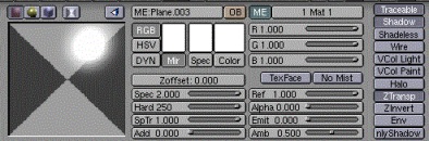
Let's take over the most challenging part, the material properties. Set immediately the size of the speculars Spec: 2.000 and their hardness Hard: 250, those parameters being the higher that Blender can allow us to this day. We now have a material that reflects a lot outter lights, very handy for simulating glass ! But we still have to make this material translucent.
To do this, lower the value of the slider Alpha: 0.050 and activate the 'Ztransp' button. At last, give some interesting spectral transparency to your glass with SpTr 1.000 and Ref 1.000.
 |
 |
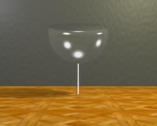
An intermediate rendering will show that the result is satisfying enough in most cases where glasses are not in the foreground nor the main subject of your scene. However, the result is very dependant to the quality of lighting and the angle of view of the scene, so feel free to do as many rendering with different viewing angles as necessary !
Note also that our glass still don't have any especially realistic look. We will see in the next step a very simple trick that will enhance and give a more striking look to our material !
S t e p 4 :
We will add a texture to our material, in order to affect the color, reflection or transparency (alpha) values of our glass. The results will certainly not be realistic, but will appear realistic enough to please the eye of an artist.
First make sure that the glass is selected, and then call the Texture Buttons ("F6"-KEY). Add a new texture with the button. Feel free to rename this texture 'Alpha' or something like this. Choose 'Blend' as texture type and 'Halo' as blending method.
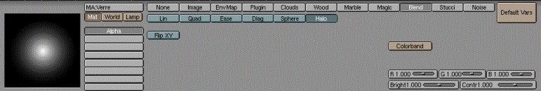
Call back the Material Buttons ("F5"-KEY). The Alpha: 0.050 value that we chose in the previous step would have been good enough if we wouldn't go further. But in this specific step, we will choose Alpha: 0.000 because it will give us far better results later.
Let assign the texture to the proper canal. Fist of all, define the color of the texture with the R, G and B sliders, that all should have a value of 1.000. Other values prove to be great for colorful glasses. Feel free to try any hue of blue, green, yellow... Then, tell Blender that the texture should affect the Col and Alpha channels of your material. Leave the Col 1.000 slider to its default value (of course, you can decide to decrease this value if you want to get colored glass, according to your taste and the needs of your scene) but decrease the Var 1.000 slider to the Var 0.5000 value, which should soften the alterations due to the activation of the Alpha channel. The mapping of the texture should conform to the following settings, for a better rendering effect : mapping along Nor and Sphere, and remapping of the texture components in the Z only direction (the other directions are desactivated : thus, you can be sure that the texture color will only affect the outter edges of your rounded object).
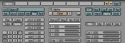
Feel free to play with the Mul, Add and Sub buttons, as their results can be far more interesting than the standard Mix button. Try also to activate the Emit channel, in addition to the Col and Alpha channels. The look of your glass will be slightly enhanced, at the price of a light radiance in the dark parts of your scene (this solution is only appropriate in well lighted scenes, such as the one depicted bellow!).
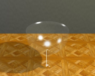
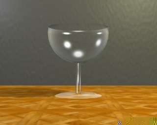
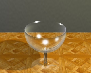
Anyway, we are now able to produce the following results, far more satisfying than the results fro the previous step, aren't they ?
 |
 |
We have now reached the limits of my skills on this topic, and we can hardly do better during this tutorial. However, there's still something that we can improve to give our scene a better realism. Let's move on the next step !
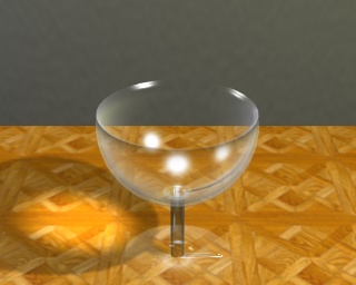
There's a major topic that haven't been discussed yet, while it has a clear influence ont the rendering samples showed earlier in the tutorial : lighting !
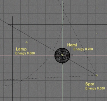
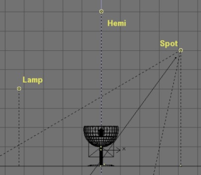
For this scene, I added a lamp (Energy 0.500) to the left of the glass, a Hemi (Energy 0.700) above it, and a spot (Energy 0.500, 'Only shadow' turned on), slightly on the foreground and to the right of the glass, as shown on the two following pictures.
 |
 |
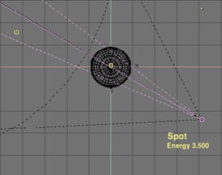
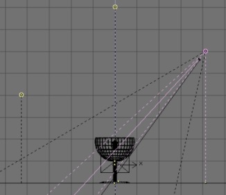
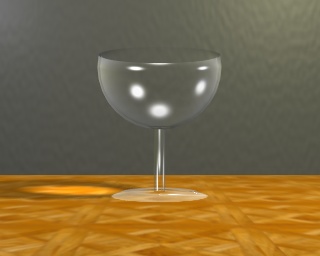
As a last step to enhance the realism of our scene, we will simulate the appearance of caustics, e.g. the flocks of light that show in the shade of a glass object, light warped and concentrated by the roundness and thickness of the glass. In order to simulate this phenomenon, move the glass on the second layer of the scene ("M"-KEY and then select the second little squarre from the left). Now select the spot and make a copy of it with SHIFT-"D" and call the Lamp Buttons ("F4"-KEY). Deselect the 'Only Shadow' button but select 'Layer' instead, because you don't want the glass to be lighted by the light. Set the lamp parameters as shown hereafter, and especially the Energy 3.500 and SpotBl 1.000 parameters.
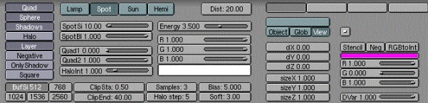
You will certainly have to make many intermediate renderings in order to set the correct location (regarding Loc and Rot) and the SpotSi that you need for your scene. The spot should point a the very heart of the glass' shade ! Within a few guess-and-try, you sould be able to find the most visual striking location, which should make its way through the geometrical center of the glass ball.
 |
 |
You now have a very last render to do in order to enjoy the result, which should be satisfying enough until NaN develops for Blender some control over indices of refraction ! We are yet a long step from absolute realism, but this trick should be sufficient to lure the non-expert into a good illusion of reality.
 |
 |
L a s t w o r d s f r o m t h e a u t h o r :
* about refraction: a common method used to fake refraction (the bending of objects seen through the curves surfaces of a glass) is to apply to the object an EnvMap texture map, and to set in the Material Buttons (F5-KEY) negative values of SizeX, SizeY and above all SizeZ (a 'minus' sign inverts the picture ; thus SizeY -1 inverts the mapped texture upside-down). For instance, we commonly see SizeZ -5.000 as a starting work value. The mapping should be done with the Nor or Ref toggled on instead of the default traditional Orco button. However, the refractions resulting from this method are barely realist or satisfying, from my point of view, and ask for tremendous tweaking to finally get parameters like SizeX -0.1, SizeY -0.1 and SizeZ -2.5. The more strange is that the experienced user of this method render similar pictures on a raytracers in order to examine the refraction map to achieve, and then tweak the SizeZ and other parameters until the achieve a similar result with the scanline mode of Blender. Having not a raytracer nor the skill to use one, I never got satisfying results while faking refractions this way. If you manage to do it, remember me ! ;o)
* about caustics : according to the shape of your glass object, you could have to use many spots in order to light the shade of your object a likely luminous area. Don't forget that you can get a square spot section by toggling on the 'Square' button ! In the folling picture, I achieved caustics with the proper stacking of many square spots.