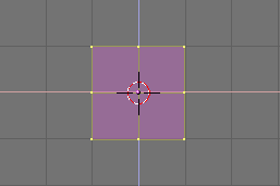
Figure 4. Our cube in Edit Mode, all vertices selected
![]()
Figure 5. The Edit Buttons Window button.
Gingerbread Man
Relevant to Blender v2.31
Blender Documentation Volume I - User Guide: Last modified September 01 2004 S68
http://www.blender.org/modules/documentation/htmlI/c1205.html
Building the body
1. Change to the front view with NUM1 and add a cube by pressing SPACE and selecting menu Add, submenu Mesh, sub-submenu Cube. (In the book we will use SPACE>>ADD>>Mesh>>Cube as shorthand for these kinds of actions).
2. A cube will appear (Figure 4). This newly added cube is in Edit Mode, a mode in which you can move the single vertices that comprise the mesh. By default, all vertices are selected (highlighted in yellow - unselected vertices are pink).
Figure 4. Our cube in Edit Mode, all vertices selected |
Figure 5. The Edit Buttons Window button. |
3. We will call our Gingerbread man "Gus". Our first task is to build Gus's body by working on our cube in EditMode. To see the Blender tools that we'll use for this purpose, press the button showing a square with yellow vertices in the Button window header (Figure 5), or press F9.
4. Now locate the Subdivide button in the Mesh Tools panel and press it once (Figure 6). This will split each side of the cube in two, creating new vertices and faces (Figure 7).
Figure 6. The Edit Buttons window for a Mesh.
Figure 7. The cube, subdivided once. |
5. With your cursor hovering in the 3D window press the "A" KEY to deselect all elements. Vertices will turn pink. Now press the "B" KEY; the cursor will change to a couple of orthogonal grey lines. Move the cursor above the top left corner of the cube, press and hold LMB (default behavior for a Mac one button mouse), then drag the mouse down and to the right so that the grey box encompasses all the leftmost vertices. Now release the LMB. This sequence, which lets you select a group of vertices in a box, is summarized in Figure 8. Tip - Box Select |
Figure 8. The sequence of Box selecting a group of vertices.
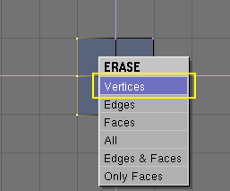
6. Now press "X" KEY and, from the menu that pops up, select Vertices to erase the selected vertices (Figure 9).
Figure 9. The pop-up menu of the Delete ("X" KEY) action. |
Tip - Undo Mesh Undo works only in Edit Mode and only for one mesh at a time. Undo data is not lost when you switch out of Edit Mode, only when you start editing a different mesh. Another way to revert to the previously saved state is to press ESC in the middle of an action. This cancels the action, reverting to the previous state. |
7. Now, using the sequence you just learned, Box Select the two top-rightmost vertices (Figure 10, left). Press the "E" KEY and click on the Extrude menu entry to extrude them. This will create new vertices and faces which you can move and which will follow the mouse. Move them to the right.
8. To constrain the movement horizontally or vertically, click MMB (on a Mac keep the Alt key pressed in combination with the Shift and Ctrl keys to get this behaviour when you press the mouse button) while moving. You can switch back to unconstrained movement by clicking MMB again. Alternatively you can use "X" KEY to constrain movement to x axis, 'Y" KEY for y axis and so on.
9. Let's create Gus's arms and legs. Move these new vertices one and a half squares to the right, then click LMB to fix their position.
10. Extrude again with the "E" KEY then move the new vertices another half square to the right. Figure 10 show this sequence.
Figure 10. Extruding the arm in two steps.
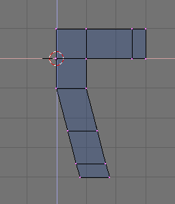
11. Gus should now have a left arm (he's facing us). We will build the left leg the same way by extruding the lower vertices. Try to produce something like that shown in Figure 11.
We use the Extrude tool three times to produce the leg. We don't care about elbows, but we will need a knee later on!
Figure 11. Half body |
Coincident vertices If you extrude, and in the process of moving you change your mind and press ESC to recover, the extruded vertices will still be there, in their original location! While you can move, scale, or rotate them by pressing the "G" KEY, you probably don't want to extrude them again. To fully undo the extrusion, look for the Remove Doubles button, highlighted in Figure 12. This will eliminate coincident vertices. |


Figure 12. The Edit Buttons window.
Now we'll create the other half of Gus:
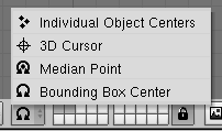
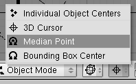
12. Select all vertices (the "A" KEY) and choose the 3D Cursor entry in the Rotation/Scaling Pivot Menu of the 3D Window header. (Figure 13).
13. Press SHIFT-D to duplicate all selected vertices, edges, and faces. The new objects are in Grab mode, press ESC to exit from this mode without moving the vertices.
14. Press the "M" KEY to open the Mirror Axis Menu. Choose Global X. The result is shown in Figure 14.
Figure 13. Setting the reference center to the cursor. |
Figure 14. Flip the copy of the half body to obtain a full body. |
15. Deselect all then reselect all by pressing the "A" KEY twice, then eliminate the coincident vertices by pressing the Remove doubles button (Figure 12). A box will appear, notifying you that eight vertices have been removed.
Reference center
In Blender, scaling, rotating and other mesh modifications occur either with respect to the cursor position, the object's center, or the barycenter (center of mass) of the selected items, depending upon which entry of the Rotation/Scaling Pivot Menu (Figure 13) is active. The crosshair button selects the cursor as reference.
Moving the cursor
To place the cursor at a specific grid point, position it next to where you want it and press SHIFT-S to bring up the Snap Menu. The entry Curs->Grid places the cursor exactly on a grid point. The Curs->Sel places it exactly on the selected object. The other entries move objects other than the cursor.
Gus Needs a head:
1. Move the cursor so that it is exactly one grid square above Gus' body (Figure 15, left). Add a new cube here (SPACE>>ADD>>Mesh>>Cube).
2. Press the "G" KEY to switch to Grab Mode and move the newly created vertices down, constraining the movement with MMB, for about one third of a grid unit (Figure 15, right).
Figure 15. The sequence of adding the head.
3. This produces a rough figure at best. To make it smoother, locate the SubSurf Toggle Button (Figure 16) in the Mesh panel and switch it on. Be sure to set both the two NumButtons below to 2.
SubSurfacing is an advanced modelling tool, it dynamically refines a given coarse mesh creating a much denser mesh and locating the vertices of the finer mesh so that they smoothly follow the original coarse mesh. The shape of the Object is still controlled by the location of the coarse mesh vertices, but the rendered shape is the smooth, fine mesh one.


Figure 16. The Edit Buttons window.
4. Switch out of Edit Mode (TAB) and switch from the current default Wireframe mode to Solid mode with "Z" KEY to have a look at Gus. He should look like Figure 17.
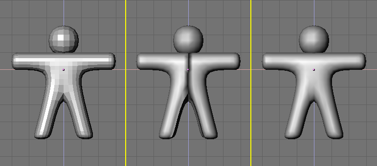
Figure 17. Setting Gus to smooth.
5. To make Gus look smooth, press the SetSmooth button in Figure 16. Gus will now appear smooth but with funny black lines in his middle (Figure 17, middle). These lines appear because the SubSurfed finer mesh is computed using information about the coarse mesh normal directions, which may not be self consistent, that is, some face normals might point outward, some inward, if extrusions and flippings have been made. To reset the normals, switch back to Edit Mode(TAB), select all vertices ("A" KEY), and press CTRL-N. Click with LMB on the Recalc normals outside box which appears. Now Gus should be nice and smooth, as shown in Figure 17, right.
6. Press MMB and drag the mouse around to view Gus from all angles. Oops, he is too thick! To fix that, switch to side view NUM3. Now, switch to Edit Mode (if you are not there already), then back to Wireframe mode ("Z" KEY), and select all vertices with "A" KEY (Figure 18, left).
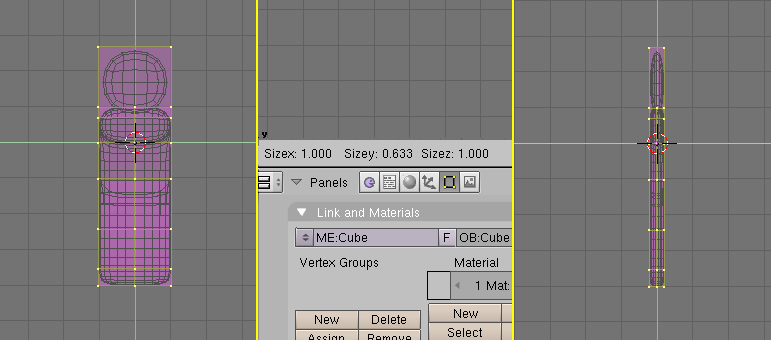
Figure 18. Slimming Gus using constrained scaling.
Let's make Gus thinner:
1. Press "S" KEY and start to move the mouse horizontally. (Click MMB to constrain scaling to just one axis or press "Y" KEY to obtain the same result). If you now move the mouse toward Gus he should become thinner but remain the same height.
2. The three numbers on the 3DWindow toolbar show the scaling factor. Once you constrained scaling, only one of these numbers will vary. Press and hold CTRL. The scale factor will now vary in discrete steps of value 0.1. Scale Gus down so that the factor is 0.2, then set this dimension by clicking LMB.
3. Return to Front view and to Solid mode ("Z" KEY), then rotate your view via MMB. Gus is much better now!
Let's see what Gus looks like
We're just about ready to see our first rendering, but first, we've got some work to do.
1. SHIFT-LMB on the top right small button of the layer visibility buttons in the 3DWindow toolbar (Figure 19) to make both Layer 1 (Gus's layer) and Layer 10 (the layer with the camera) visible.
Figure 19. Making both layer 1 and 10 visible. |
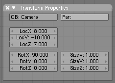
Figure 20. The Panel for numerical input of object position/rotation |
Remember that the last layer selected is the active layer, so all subsequent additions will automatically be on layer 10.
2. Select the camera (RMB) and move it to a location like (x = 7, y = -10, z = 7). Do this by pressing "G" KEY and dragging the camera while keeping CTRL pressed to move it in steps of 1 grid unit.
Entering precise locations and rotations
If you prefer to enter numerical values for an object's location you can do so by pressing "N' KEY and modifying the NumButtons in the Panel that appears (Figure 20). Remember to press OK to confirm your input.
3. To make the camera point at Gus, keep your camera selected then select Gus via SHIFT-RMB. The camera should be magenta and Gus light pink. Now press CTRL-T and select the Old Track entry in the pop up. This will force the camera to track Gus and always point at him. This means that you can move the camera wherever you want and be sure that Gus will always be in the center of the camera's view.
Tracking
If the tracking object already has a rotation of its own, as is often the case, the result of the CTRL-T sequence might not be as expected. If it is not, select the tracking object (in our example the camera), and press ALT-R to remove any object rotation. Once you do this the camera will really track Gus.
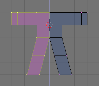
Figure 21 shows top, front, side and camera view of Gus. To obtain a camera view press NUM0.


Figure 21. Camera position with respect to Gus.
Now we need to create the ground for Gus to stand on.
1. In top view (NUM 7), and out of Edit Mode, add a plane (SPACE>>ADD>>Mesh>>Plane).
It is important to be out of Edit Mode, otherwise the newly added object would be part of the object currently in Edit Mode, as it was for Gus' head when we added it. If the cursor is where Figure 21 shows, such a plane would be in the middle of Gus's body.
2. Switch to Object Mode and Front view (NUM1) and move ("G" KEY) the plane down to Gus's feet, using CTRL to keep it aligned with Gus.
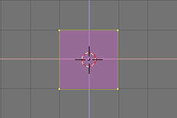
3. Switch the reference center from cursor (where we set it at the beginning) to object by pressing the highlighted button Figure 22.
4. Go to Camera view (NUM 0) and, with the plane still selected, press SKEY to start scaling.
Figure 22. Set the reference center to Object center. |
5. Enlarge the plane so that its edges extend beyond the camera viewing area, as indicated by the outer white dashed rectangle in Camera view.
|
Now, some light!
1. In Top view (NUM 7), add a Lamp light (SPACE>>ADD>>Lamp) in front of Gus, but on the other side of the camera; for example in (x = -9, y = -10, z = 7) (Figure 23).


Figure 23. Inserting a Lamp.
2. Switch to the Lamp Buttons in the Shading context via the button with a lamp in the Button Window toolbar (Figure 24) or F5.
![]() Figure 24. The Lamp Buttons window button.
Figure 24. The Lamp Buttons window button.
3. In the Buttons Window, Preview Panel, press the Spot toggle button to make the lamp a Spotlight (Figure 25) of pale yellow (R=1, G=1, B=0.9). Adjust ClipSta: Num Button to 5, Samples: to 4, and Soft: to 8.


Figure 25. Spot light settings.
4. Make this spotlight track Gus just as you did for the camera by selecting Spot, SHIFT, then Gus, then by pressing CTRL-T. If you added the spot in Top View you should not need to clear its rotation via ALT-R.
5. Add a second lamp in the same location as the spot, and again in Top View, with (SPACE>>ADD>>Lamp). Make this lamp a Hemi lamp with energy of 0.6 (Figure 26).


Figure 26. The Hemi lamp settings
Two lamps?
Use two or more lamps to help produce soft, realistic lighting, because in reality natural light never comes from a single point.
We're almost ready to render.
1. As a first step, go to the Scene context and Render buttons by pressing the image-like icon in the Button window toolbar (Figure 27) or F10.
![]() Figure 27. The Rendering buttons window buttons.
Figure 27. The Rendering buttons window buttons.
2. In the Render Buttons, Format Panel, set the image size to 640x480 with the Num buttons at the top right. In the Render Panel set the Shadows Toggle Button top center to On, and the OSA Toggle Button center-left to On as well (Figure 28). These latter controls will enable shadows and oversampling (OSA) which will prevent jagged edges.


Figure 28. The Rendering Buttons window
Now press the RENDER button or F12. The result, shown in Figure 29, is actually quite poor. We still need materials, and lots of details, such as eyes, and so on.
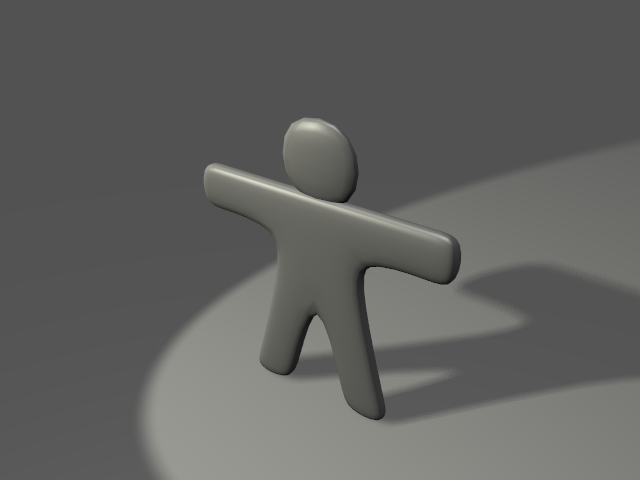
Figure 29. Your first rendering. Congratulations!
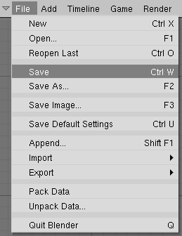
Saving Blender does automatic saves into your system's temporary directory. By default, this happens every four minutes and the file name is a number. Loading these saves is another way to undo unwanted changes. |
Figure 30. The Save menu.
|
Materials and Textures
It's time to give Gus some nice cookie-like material:
1. Select Gus. Then, in the Button Window header, select the Shading Context by pressing the red dot button (Figure 31) or using the F5 key.
![]() Figure 31. The Material Buttons window Button.
Figure 31. The Material Buttons window Button.
2. The Button window will be almost empty because Gus has no materials yet. To add a material, click on the Menu Button in the Material Panel (the one with two triangles, pointing up and down) and select Add New (Figure 32).
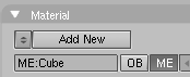 Figure 32. The Material Menu button.
3. The Buttons window will be populated by Panels and Buttons and a string holding the Material name, "Material" by default, will appear next to the white square button. Change this to something meaningful, like GingerBread.
4. Modify the default values as per Figure 33 to obtain a first rough material.


Figure 33. The Material Buttons window and a first gingerbread material.
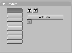
5. Press the Menu Button in the Textures Panel area (Figure 34) and select Add new. We're adding a texture in the first channel. Call it "GingerTex."
Figure 34. The Textures menu button in the Material Buttons |
Figure 35. The Texture Buttons window Button. |
6. Select the Texture Buttons by clicking the button in Figure 35 or by pressing F6.
7. From the columns of Toggle Buttons which appear in the Texture panel select Stucci and set all parameters as in Figure 36.


Figure 36. The Texture Buttons window with a stucci texture.
8. Return to the Material buttons (F5) and set the Map Input and Map To tabs of the Texture Panel as in Figure 37. Release the Col Toggle Button and set the Nor Toggle Button, then raise the Nor slider to 0.75. These changes will make our Stucci texture act as a "bumpmap" and make Gus look more biscuit-like.
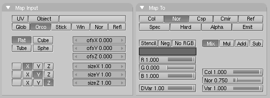
Figure 37. Settings for the Stucci texture in the Material Buttons window.
9. Now add a second texture, name it "Grain," and make it affect only the Ref property with a 0.4 Var (Figure 38). The texture itself is a plain Noise texture.


Figure 38. Settings for an additional Noise texture in channel 2.
10. Give the ground an appropriate material, such as the dark blue one shown in Figure 39.


Figure 39. A very simple material for the ground.
To give some finishing touches we'll add eyes and some other details.
1. First make Layer 1 the only one visible by clicking with LMB on the layer 1 button (Figure 40). This will hide the lamps, camera, and ground.
![]() Figure 40. Layer visibility buttons on toolbar.
Figure 40. Layer visibility buttons on toolbar.
2. Place the cursor at the center of Gus's head. (Remember that you are in 3D so be sure to check at least two views to be sure!)
3. Add a sphere (SPACE>>ADD>>Mesh>>UVsphere). You will be asked for the number of Segments: (meridians) and Rings: (parallels) into which to divide the sphere. The default of 32 is more than we need here, so use a value of 16 for both. The sphere is in the first image at the top left of the sequence in Figure 41.
4. Scale the sphere down ("S" KEY) to a factor 0.1 in all dimensions, then switch to side view (NUM 3) and scale it only in the horizontal direction ("Y" KEY) a further 0.5 (see the second two images in Figure 41).
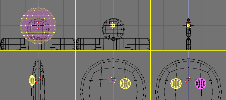
Figure 41. Sequence for creation of the eyes.
5. Zoom a little if necessary via NUM+, MW, or CTRL-MMB, and drag the sphere ("G" KEY) to the left so that it is halfway into the head (as shown in the first image in the second row of Figure 41).
6. Return to front view (NUM 1) and move the sphere sideways, to the right. Place it where Gus should have an eye.
7. Flip a duplicate around the cursor by following the sequence you learned when flipping Gus's body. (Select the crosshair toolbar button, in Edit Mode "A" KEY to select all, SHIFT-D, ESC MKEY, Global X Menu entry). Now Gus has two eyes.
8. Exit Edit Mode (TAB), and place the cursor as close as you can to the center of Gus's face. Add a new sphere and scale and move it exactly as before, but make it smaller and place it lower than and to the right of the cursor, centered on the SubSurfed mesh vertex (Figure 42).
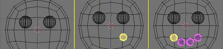
Figure 42. Creating a mouth with Spinning tools.
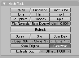
9. Now, in the Edit Buttons (F9), locate the group of buttons at bottom in the Mesh Tools Panel (Figure 43). Set Degr: to 90, Steps: to 3, and verify that the Clockwise: TogButton is on. Then, with all vertices still selected, press SpinDup. This will create three duplicates of the selected vertices on an arc of 90 degrees, centered around the cursor. The result should be Gus's mouth, like the last image of the sequence shown in Figure 42.
Figure 43. The Spin Tools buttons in theEdit Buttons window. |
Figure 44. The complete Gus! |
10. Now that you have learned the trick, add three more of these ellipsoids to form Gus's buttons. Once you have made one button, you can simply exit Edit Mode, press SHIFT-D to create a duplicate, and move the duplicate into place, as shown in Figure 44.
11. Give the eyes a chocolate-like material, like the one shown at the top in Figure 45. Give the mouth a white sugar like material, like the second one shown in Figure 45, and give the buttons a red, white, and green sugar like material. These are shown from top to bottom in Figure 45 too.

Figure 45. Some other candy materials.
Objects sharing a material
To give one object the same material as another object, select that material in the Menu list which appears when you press the Menu Button ButtonWindow Material Panel.
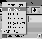 Figure 46. Selecting an existing material from the Material Menu.
12. Once you have finished assigning materials, make layer 10 visible again (you should know how), so that lights and the camera also appear, and do a new rendering (F12). The result should look more or less like Figure 47.
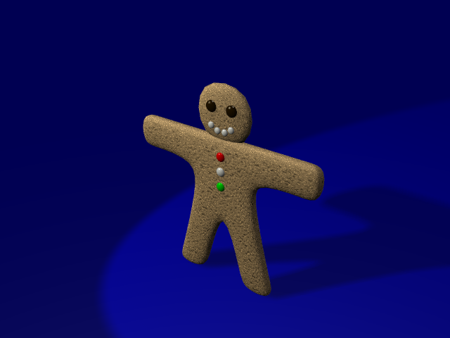
Figure 47. The complete Gus still rendering.
Save your image, if you so wish, by pressing F3. Enter the name of your image in the file window and save.
Image types and extension
You must choose the image format (JPEG, PNG, and so on) by setting it in the Rendering buttons before pressing F3 (Figure 27 in the Section called Let's see what Gus looks like) and using the Menu (Figure 48) in the Format Panel. Blender does not add an extension to the file name; you must enter one if you wish.
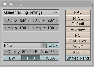
Figure 48. File type selection menu in the Rendering Buttons window.
Rigging
If we were going for a still picture, our work up to this point would be enough, but we want Gus to move! The next step is to give him a skeleton, or Armature, which will move him. This is called the fine art of rigging. Gus will have a very simple rigging: four limbs (two arms and two legs) and a few joints (no elbows, only knees), but no feet or hands. To add the rigging:
1. Set the cursor where the shoulder will be, press SPACE>>Add>>Armature. A rhomboidal object will appear, a bone of the armature system, stretching from cursor to mouse pointer. Place the other end of the armature in Gus's hand (Figure 49) with LMB. This will fix the bone and create a new one from the end point of the previous one, producing a bone chain. We don't need any other bones right now, so press ESC to exit.
Figure 49. Adding the first bone, an elbowless arm. |
Figure 50. Adding the second and third bones, a leg bone chain. |
2. Stay in Edit Mode, then move the cursor to where the hip joint will be and add a new bone (SPACE>>ADD>>Armature) down to the knee. Press LMB and a new bone should automatically appear there. Stretch this bone down to the foot (Figure 50).
Bone position
The bones we are adding will deform Gus's body mesh. To produce a neat result, try to place the bone joints as shown in the illustrations.
3. Now place the cursor in the center and select all bones with AKEY. Duplicate them with SHIFT-D and exit grab mode with ESC then flip them with "M" KEY relatively to the cursor and Global X axis as you did with meshes (Figure 51).
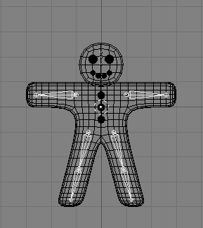 Figure 51. The complete armature after duplicating and flipping.
4. Once you've selected all of the bones ("A" KEY), the Edit Buttons window should show an Armature Bones Panel which contains the Armature buttons (Figure 52).

Figure 52. The Edit Buttons window for an armature.
5. Press the Draw Names button to see the names of the bones, then SHIFT-LMB on the names in the Edit Buttonwindow (Figure 52) to change them to something appropriate like Arm.R, Arm.L, UpLeg.R, LoLeg.R, UpLeg.L and LoLeg.L. Exit EditMode with (TAB).
Naming Bones
6. It is very important to name your bones with a trailing '.L' or '.R' to distinguish between left and right ones, so that the Action editor will be able to automatically flip your poses.
Skinning
Now we must make it so that a deformation in the armature causes a matching deformation in the body. We do this with Skinning, which assigns vertices to bones so that the former are subject to the latter's movements.
1. Select Gus's body, then SHIFT select the armature so that the body is magenta and the armature is light pink.
2. Press CTRL-P to parent the body to the armature. A pop up dialog will appear (Figure 53). Select the Use Armature entry.
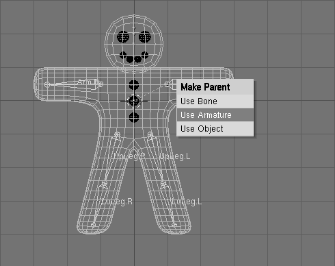
Figure 53. The pop-up menu which appears when parenting an Object to an Armature.
3. A new menu appears, asking if you want Blender to do nothing, create empty vertex groups, or create and populate vertex groups (Figure 54).
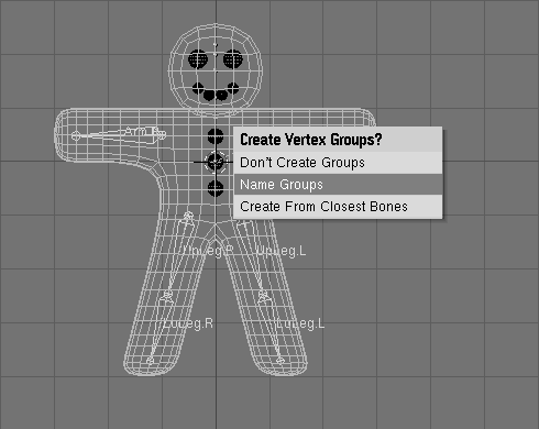
Figure 54. Automatic Skinning options.
4. We'll use the automatic skinning option. Go ahead and select Create From Closest Bones.
5. Now select only Gus's body and go to EditMode (TAB). You will notice in the Edit Buttons (F9) Window and Mesh Tools 1 Panel, the presence of a Vertex Group menu and buttons (Figure 55).


Figure 55. The vertex groups buttons in the Edit Buttons window of a mesh.
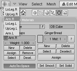
6. By pressing the Menu Button a menu with all available vertex group pops up (six in our case, but a truly complex character, with hands and feet completely rigged, can have tens of them! Figure 56). The buttons Select and Deselect show you which vertices belong to which group.
Figure 56. The menu with the vertex groups automatically created in the skinning process. |
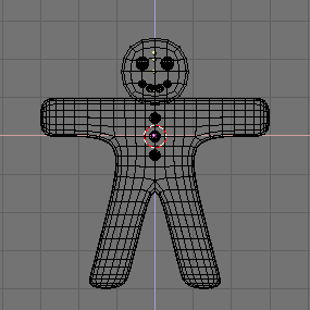
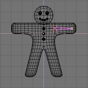
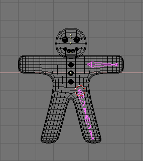
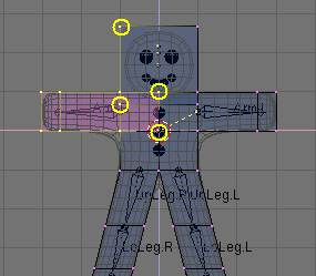
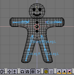
Figure 57. Gus in EditMode with all the vertices of group Arm.R selected. |
7. Select the Right arm (Arm.R) group and, with all vertices de-selected (AKEY, if needed) press Select. You should see something like Figure 57.
8. The vertices marked with yellow circles in Figure 57 belong to the deformation group, but they should not. The autoskinning process found that they were very close to the bone so it added them to the deformation group. We don't want them in this group because, since some are in the head and some are in the chest, adding them to the deformation group would deform those body parts. To remove them from the group, deselect all the other vertices, those which should remain in the group using Box selection (BKEY), but use MMB, not LMB, to define the box, so that all vertices within the box become deselected.
9. Once only the 'undesired' vertices are selected, press the Remove button (Figure 55) to eliminate them from group Arm.R.
10. Deselect all ("A" KEY) then check another group. Check them all and be sure that they look like those in Figure 58.
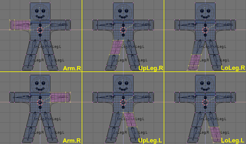
Figure 58. The six vertex groups.
Vertex groups
Be very careful when assigning or removing vertices from vertex groups. If later on you see unexpected deformations, you might have forgotten some vertices, or placed too many in the group. You can modify your vertex groups at any time.
Other details
Our deformations will affect only Gus's body, not his eyes, mouth, or buttons, which are separate objects. While this is not an issue to consider in this simple animation, it's one that must be taken into account for more complex projects, for example by parenting or otherwise joining the various parts to the body to make a single mesh. (We'll describe all of these options in detail in later Chapters).
Posing
Once you have a rigged and skinned Gus you can start playing with him as if he were a doll, moving his bones and viewing the results.
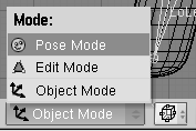
1. Select the armature only, then select Pose Mode from the "Mode" Menu (Figure 59). This option only appears if an armature is selected.
Figure 59. The toggle button to switch to pose mode in the 3D Window toolbar. |
Figure 60. You are in pose mode now! |
2. The armature will turn blue. You are in Pose Mode. If you now select a bone it will turn cyan, not pink, and if you move it ("G" KEY), or rotate it ("R" KEY), the body will deform!
Original position
Blender remembers the original position of the bones. You can set your armature back by pressing the RestPos button in the Armature Edit Buttons (Figure 52 in the Section called Rigging).
Forward and Inverse Kinematics
While handling bones in pose mode you will notice that they act as rigid, inextensible bodies with spherical joints at the end. You can actually grab only the first bone of a chain and all the other will follow it. All subsequent bones in the chain cannot be grabbed and moved, you can only rotate them, so that the selected bone rotates with respect to the previous bone in the chain while all the subsequent bones of the chain follow its rotation.
This procedure, called Forward Kinematics (FK) is easy to follow, but it makes precise location of the last bone of the chain difficult. We can use another method, Inverse Kinematics (IK) where you actually define the position of the last bone in the chain, and all the other assume a position, automatically computed by Blender, to keep the chain without gaps. Hence precise positioning of hands and feet is much easier.
We'll make Gus walk by defining four different poses relative to four different stages of a stride. Blender will do the work of creating a fluid animation.
3. First, verify that you are at frame 1 of the timeline. The frame number appears in a NumButton on the right of the Buttons Window Toolbar (Figure 61). If it is not set to 1, set it to 1 now.
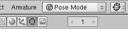 Figure 61. The current frame Num Button in the Buttons window Toolbar.
4. Now, by rotating only one bone at a time ("R" KEY), we'll raise UpLeg.L and bend LoLeg.L backwards while raising Arm.R a little and lowering Arm.L a little, as shown in Figure 62.


Figure 62. Our first pose.
5. Select all bones with "A" KEY. With the mouse pointer on the 3D Window, press "I" KEY. A menu pops up (Figure 63). Select LocRot from this menu. This will get the position and orientation of all bones and store it in a pose at frame 1. This pose represents Gus in the middle of his stride, while moving his left leg forward and above the ground.
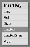 Figure 63. Storing the pose to the frame.
6. Now move to frame 11 either by entering the number in the NumButton or by pressing UP ARROW. Then move Gus to a different position, like Figure 64, with his left leg forward and right leg backward, both slightly bent. Gus is walking in place!


Figure 64. Our second pose.
7. Select all bones again and press "I" KEY to store this pose at frame 11.
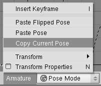
8. We now need a third pose at frame 21, with the right leg up, because we are in the middle of the other half of the stride. This pose is the mirror of the one we defined at frame 1. Therefore, return to frame 1 and, in the Armature Menu in the 3D Window header select the Copy Pose entry. (Figure 65). You have copied the current pose to the buffer.
Figure 65. Copying the pose to the buffer |
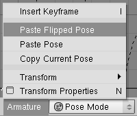
Figure 66. Pasting the copy as a new, flipped, pose. |
9. Go to frame 21 and paste the pose with the Paste Flipped Pose option in the Armature Menu (Figure 66). This button will paste the cut pose, exchanging the positions of bones with suffix .L with those of bones with suffix .R, effectively flipping it!
The pose is there but it has not been stored yet! You must press "I" KEY with all bones selected.
10. Now apply the same procedure to copy the pose at frame 11 to frame 31, also flipping it.
11. To complete the cycle, we need to copy the pose at frame 1 without flipping to frame 41. Do so by copying it as usual, and by using Paste Pose entry. End the sequence by storing the pose with "I" KEY.
Checking the animation
To preview your Animation, set the current frame to 1 and press ALT-A in the 3D window.
The single step in-place is the core of a walk, and once you have defined one there are techniques to make a character walk along a complex path. But, for the purpose of our Quick Start, this single step in- place is enough.
1. Change to the Rendering Buttons (F10) and set the animation start and end to 1 and 40 respectively (Figure 67). Because frame 41 is identical to frame 1, we only need to render frames from 1 to 40 to produce the full cycle.


Figure 67. Setting the Rendering Buttons for an animation.
2. Select AVI Raw as the file type in Format Panel (Figure 67). While this is generally not the best choice, mainly for file size issues (as will be explained later on), it is fast and it will run on any machine, so it suits our needs. (You can also select AVI Jpeg to produce a more compact file, but using lossy Jpeg compression and obtaining a movie that some external render might not be able to play).
3. Finally, press ANIM button in Anim Panel. Remember that all the layers that you want to use in the animation must be shown! In our case, these are layers 1 and 10.
Stopping a Rendering
If you make a mistake, like forgetting to set layer 10 to on, you can stop the rendering process with the ESC key.
Our scene is pretty simple, and Blender will probably render each of the 40 images in a few seconds. Watch them as they appear.
Stills
Of course you can always render each of your animation frames as a still by selecting the frame you wish to render and pressing the RENDER button.
Once the rendering is complete you should have a file named 0001_0040.avi in a render subdirectory of your current directory - the one containing your .blend file. You can play this file directly within Blender by pressing the Play button beneath the ANIM button (Figure 67). The animation will automatically cycle. To stop it press ESC.