1. Creating Groups
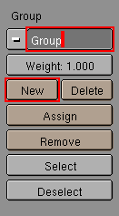
Once your armature is established, it is time to specify which bones will affect which vertices of the mesh. This is done using vertex groups. To access the vertex grouping features, select the mesh you will be deforming and enter EditMode. Switch to the EditButtons and find the "Group" column (Figure 22-5). Normally you will have one vertex group for each bone in the armature. A vertex can belong to more than one group, which is how smooth deformation is achieved. In order to be recognized by the armature, the vertex groups must have exactly the same names as the bones they are associated with (capitalization matters). To create a new vertex group, click on the "NEW" button and edit the name in the text button that will appear.
Figure 22-5. Group buttons in the EditButtons
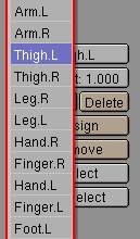
You can see a list of all of the current deformation groups by clicking on the menu next to the group name button (Figure 22-6). Selecting an item from this menu changes the active deformation group.
Figure 22-6.
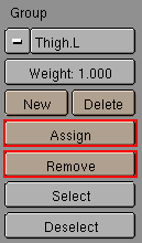
You can assign vertices to the currently active deformation group by selecting vertices and clicking the "Assign" button. The selected vertices will be assigned to the active group with the weight specified in the "Weight" slider. You can remove vertices from the current deformation group by selecting them and clicking the "Remove" button.
Create vertex groups for all of the bones in your armature (making sure the names of the groups and bones match) and assign vertices to the appropriate groups. Make sure that every vertex is affected by at least one bone. For this "first pass" of the deformation process, try to keep things simple by leaving the weight set to "1.000" and avoid having vertices being assigned to more than one group.
2. Attaching the Mesh to the Armature
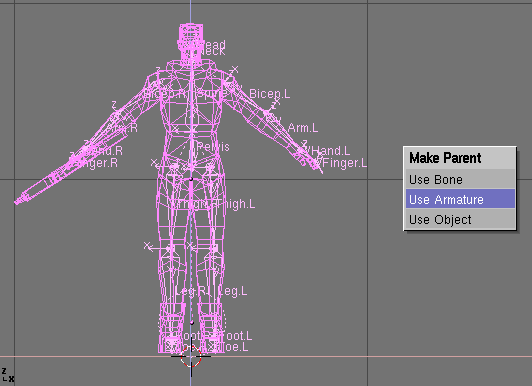
At this point, you are ready to attach the mesh to the armature. Make sure that the mesh and the armature are correctly lined up and that you are not in EditMode (Figure 22-7). Select the mesh first and while holding SHIFT, select the armature and press CTRL-P->"Use Armature".
Figure 22-7. Lined up Mesh and Armature
3. Testing the Skinning
Once you have attached the mesh to the armature, you are ready to start testing the deformation. It often takes a fair amount of tweaking to get satisfying results. You want to avoid the excessive pinching or stretching that can occur when vertices are not assigned to the right bones. We'll spend more time on that later. For now, we'll take a look at how to pose the armature, which is a skill needed for testing the deformation.
4. PoseMode
In addition to EditMode, armatures have a PoseMode. This is used to position bones within the armature. Setting keyframes in PoseMode defines an "action" for the armature, and the game engine will use these actions to animate the character.
Note that only transformations performed in PoseMode will be incorporated into the action (and therefore the game engine). Rotations, scalings and translations performed in ObjectMode cannot be recorded in actions.
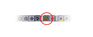
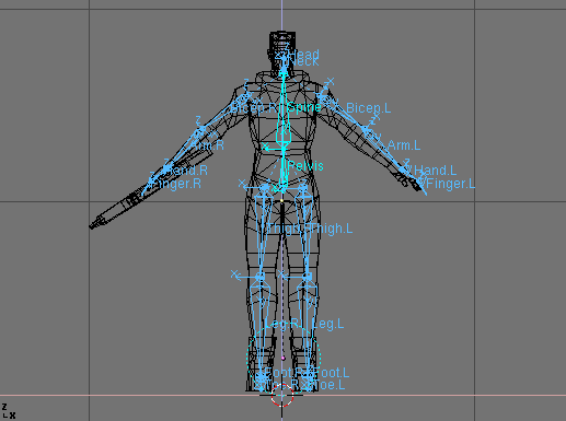
You can toggle in and out of PoseMode by selecting an armature and pressing CTRL-TAB or by clicking on the PoseMode icon in the 3DWindow Header bar. When in PoseMode, the armature will be drawn in blue, with selected bones drawn in a lighter shade.
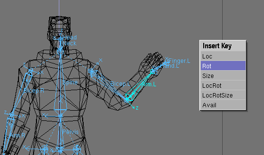
Figure 22-8. Armature in PoseMode
To manipulate bones in PoseMode, select bones by using RMB on them and use the standard transformation keys for scaling, rotation and translation. Note that you cannot add or remove bones in PoseMode, and you cannot edit the armature's hierarchy.
At any time, you can clear the pose you have made and return to the armature's rest position by clearing the rotation, scaling and translation components using ALT-R, ALT-S and ALT-G respectively.
You can set keyframes for a pose by selecting one or more bones and pressing IKEY. and choosing one of the transformation channels to key from the pop up menu.
Figure 22-9. Selected "Arm.L" bone